 Studios
-
 Support
 -
 Contact us
 -
 News
News -
 Products
 -
0
 Cart
Cart
![]() Studios
Studios
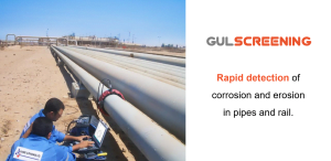
GUL Screening is normally used to rapidly and cost effectively locate and classify areas of damage on a pipeline. Since waves are sent along the pipe from the sensor location, 100 percent coverage (even of inaccessible areas) can be obtained.
Originally designed for detection of corrosion under insulation (CUI), the application of GUL Screening has expanded into many other areas. It is also widely used to inspect for corrosion at pipe supports, at air/soil interfaces, in buried sections, on overhead lines, and many more.
Please see the Screening Overview page or Screening Case Studies page for more information.
Wavemaker® is the product name of the guided wave system that GUL Screening utilises
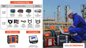
The system comprises of 3 primary components: a sensor (the transducer ring), a Wavemaker® instrument, and a computer running the analysis and reporting software. Details of these can be found on the Wavemaker System page.
All three names refer to the same general inspection concept. However, we feel that GWT and GUL Screening most accurately describe the method and system being used. More information is available on the Terminology page.
GUL Screening has solutions for pipes with diameters from 0.75 inch (19.05 mm) and above. The applicable pipe wall thicknesses range from 3 mm to 70 mm (1/8 to 2.75 inch). We have a range of transducer ring types and sizes to meet your inspection requirements. Please see our Catalogue Product & Services PDF for standard products or contact us separately for custom sizes.

GUL Screening can be used on almost all metal pipes. However, it currently cannot be used on plastic pipes.
See the Applicable Materials page for more information.
Guided waves are those waves whose propagating characteristics are greatly influenced by the geometry of the structure in which they exist and not just the mechanical properties of the material. Since the structure ‘guides’ the waves, the waves are very sensitive to any change in the geometry of the structure (for example a loss of section caused by corrosion). Therefore, even at low frequencies, very small changes cause reflections that can be detected and analyzed. This allows for 100 percent coverage even far from the sensor. More in-depth information can be found on the What are guided waves? page.
GUL screening uses the T(0,1) torsional mode instead of the alternatives for several reasons including:
More detailed information is available on the Why Torsional page.
The torsional T(0,1) guided wave is generated within the pipe, via a ring of transducers. The guided wave will travel away in both direction from transducer ring at a speed of approximately 3,250 m/s (10,662 ft/s). The waves will be reflected from both pipe features (e.g. welds, supports, flanges) and defects (e.g. corrosion, erosion, mechanical damage), causing the signal to travel back towards the transducer ring. GUL Screening works by collecting and analysing the properties of these reflected waves (e.g. time of arrival, torsional and flexural contents).
The A-scan is a plot that shows the reflected guided wave signals against the pipe axial distance. The black and red signals are the torsional and flexural components of the reflected signal. The x-axis represents the relative distance of the signal from the transducer location. In other words x = 0 m is the transducer ring location and the positive and negative distances represents the forward and backwards direction from the transducer ring.
The DAC curves provide a quantitative link (or calibration curve) between the signal amplitude and cross-sectional area change (CSC) within the pipe. so that we can ultimately quantify the extent of the damages in terms of pipe CSC. An accurate DAC curve is required to call the severity of defects in pipes
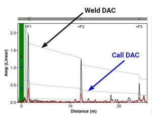
The figure above shows an A-scan with the Weld and Call DACs labelled. In most inspections, the Weld DAC is established by using either weld size parameters or via the Absolute Calibration method. This results in a calibrated Call DAC, which can be used to estimate defect severity and determine end of inspection test range.
The Call DAC is the threshold level that is used to determine the defect severity if found. Typically, it is set between 1% and 6% CSC according to the sensitivity requirement of the inspection.
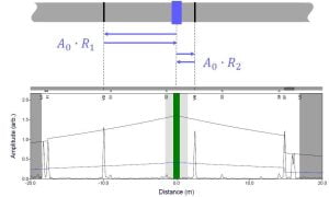
Absolute Calibration is GUL’s patented method of calibrating the DAC curves. Put simply, this method uses reverberation signals from pipe features, such as welds or flanges, to rapidly and accurately calibrate the DAC curves.
What is Unrolled Pipe Display in GUL Screening?
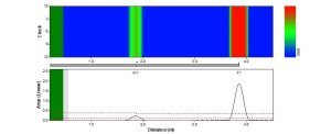
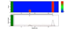
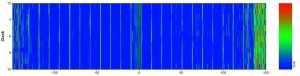
The Unrolled Pipe Display is a colour plot that shows the guided wave reflection amplitude as a function of axial distance and circumferential position. This plot is generated by using a proprietary algorithm that enables total focusing of the guided wave signals at all locations (within the valid inspection range), analogous to Total Focusing Method in phased array UT.
Using post processing to produce the unrolled display avoids the need to collect additional data making the inspection faster.
The systems sends and received multiple guided wave modes and frequencies. Different types of pipe features and defects reflect the guided wave modes and frequencies differently. These allow characteristics allow a trained inspector to infer the type of feature that caused the reflection. There are several Level 1 and 2 GUL Training (GULT) courses that are designed to equip inspectors with the skills and knowledge to confidently and competently perform this task for different application areas.
The inspector will typically also use their knowledge of the site, drawings, and various visual clues to confirm any reflections that have been identified and provide further information about the integrity of the pipe.
The detection sensitivity can be adjusted by using different transducer modules and software configurations. The HD (high definition) rings generally can see smaller defects (for example small pits) than the standard modules. However, the inspection range is reduced, especially if the pipe is generally corroded (a lot of energy is reflected back from each of the small (not always important) corrosion locations) or has a thick coating. Therefore, the inspector will normally choose a setup based the type of defect that is expected.
On clean pipes where localized pitting is the main concern, 1% cross-sectional area change (CSC) would be a standard detection level target. However, for buried pipes where gross external corrosion is the main concern, a 5% CSC will normally be used that will allow the inspection range to be extended. Once a result has been collected, it can be easily analyzed to mark the relative noise levels and the height of any reflections that can be reliably detected above this noise level. The absolute calibration method allows this to be accurately converted into an equivalent cross sectional changes level for that test so that the sensitivity achieved for each test can be known and validated.
If measuring from the transducer ring (sensor) location, the accuracy of defect location is ±100 mm (approx. 4 inches) for the typical variations in pipe temperature and the typical inspection ranges. By measuring the relative distance from the closest visible feature, defects can be located much more precisely.
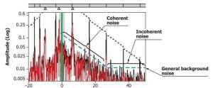
There are 2 types of noise considered in GUL Screening, namely coherent and incoherent noise. Coherent noise is not random and can be attributed to the pipe condition, corrosion, scales and other features that causes unwanted guided wave scattering. Incoherent noise is random (i.e. can be reduced by signal averaging) and is attributed to background and electrical noise.
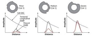
After identifying a defect in the result, the defect can be ranked using user defined categories (the defaults are Minor, Medium and Severe). The classification is determined on the depth of defect, which is roughly estimated by considering the total cross-sectional area change (CSC) and distribution (circumferential extent) of this loss and assuming a defect shape. The inspector will use the relative heights of different guided wave modes (compared to the DAC curves) to determine the classification.
The inspection range can either be determined by the intersection of the Call and Detection Threshold (DT) or by limited by certain pipe features such as flanges or elbows. The DT is typically defined as 6 dB above the noise level.
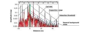
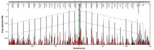
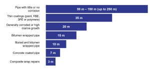
In ideal circumstances, the test range can be more than 200 meters (656 feet) in each direction. However, this may not always be the case as the inspection range can be limited by attenuation due to pipeline properties (coatings, surrounding environment and existing pipe metal condition) or features such as bends or flanges.
The figure below provides a guide to the typical and average inspection range for GUL Screening.
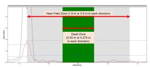
The dead zone is indicated by the green area in the A-scan. Data is not available in this area because the transducers are still transmitting the signal and not receiving any (pulse-echo configuration).
The near field zone is the gray area next to the dead zone in the A-scan. Data is available in this region, but should not be used for defect detection because the system is transitioning from a transmit to a receive mode, which affects the received amplitudes.
The size of the dead zone and near field zone are a affected by the frequency of the guided wave signal (higher frequencies = smaller zones). It can be estimated that the length of dead zone and near-field zone are 0.275 m (1 foot) and 0.9 m (3 feet) per sensor direction respectively.
GUL Screening can be used for detection of:
GUL Screening can be used to inspect:
| Pipe Feature |
| |||
|---|---|---|---|---|
| Girth Welds |
| |||
| Spiral Welds |
| |||
| Simple Support |
| |||
| Drain/Vent |
| |||
| Clamped Supports |
| |||
| Welded Supports |
| |||
| Concrete Anchor Supports |
| |||
| Bushings |
| |||
| Pipe Elbows |
| |||
| Pipe Caps |
| |||
| Crosses |
| |||
| Flanges |
| |||
| Concentric Reducers |
| |||
| Nipples |
| |||
| Branch (Tee) |
| |||
| Unions |
| |||
| Valves |
| |||
| Link Seal |
|
| Transducer Ring Type | Pipe Operating Temperature Range |
|---|---|
| Compact, EFC Inflatable, HD Inflatable, HD Solid, Solid | -40°C to +150°C |
| HT Inflatable, HT Solid, HT‑HD Solid | -40°C to +350°C |
GUL Screening is most effective when used on pipes with coatings or paint thicknesses of up to 1 mm (3/64 inch).
Yes. Please see link below:
GUL Case Studies
Using the default data collection procedures, data collection with the Wavemaker G4MINI typically takes 2 minutes.
GUL Screening is currently not applicable to finned tubes or pipes due to the relatively large coherent noise generated by the fins’ reflections.
Reducers can often be inspected through, depending on the relative size change. For example, NPS14:NPS12 (DN350 to DN300) has little effect, whereas NPS4:NPS2 (DN100 to DN50) would result in a more significant signal loss.
Bends are similar—there is always some loss of signal, and the tighter the bend, the greater the loss. Data analysis allows the loss level to be quantified so that the level of sensitivity obtained around the bend is known.
GUL Screening generates an Unrolled Pipe Display, which appears very similar to a conventional corrosion map. However, it shows cross‑sectional area change (CSC) and does not directly map wall thickness. Nevertheless, it will locate areas of wall loss and we are able to estimate remaining wall for these areas.
Yes. To estimate the inspection range, we would need to know the thickness of the concrete lining and the pipe wall thickness, as well as the information on the condition of the concrete bond to the pipe, or if bonded at all.
GUL Screening is not designed for measuring stress in pipes.
You only need to purchase the sizes required for your project scope, when investing in a Wavemaker® Screening System, ensuring a cost‑effective solution.
Rings are designed for a specified nominal pipe size (NPS) and can tolerate minor differences from the intended pipe diameter. This means that to inspect an NPS 8 pipe, you would need an NPS 8 Ring, which ensures precise and accurate inspection results.
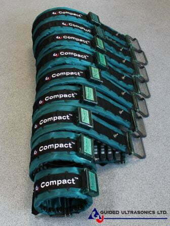
Solid Rings are available for NPS 2 to NPS 8, while Inflatable Rings are available from NPS 6 onwards. Commonly used sizes of Solid Rings are NPS 2, NPS 3, and NPS 4. The most frequently used sizes for Inflatable Rings are between NPS 6 and NPS 24. The adjacent photograph shows Compact™ Rings for NPS 6, 8, 10, 12, 14, 16, 18, 20, and 24.
Rings can be produced for larger pipe diameters. However, two inflatable rings can also be combined to form a larger one. Visit "Combining Rings" for more details.

Combining two Inflatable Rings to form a larger one is a cost-effective solution. This capability significantly reduces the need to purchase additional rings for inspecting pipes larger than NPS 24.
It is important to remember that sufficient modules to populate both rings must be available and that most combinations require using long arms on one ring.
The adjacent photograph illustrates an example: Two Compact™Rings, one for NPS 30 and the other for NPS 26, are combined to allow inspection of an NPS 60 pipe.
For more detailed information, please visit "Combining Rings ".
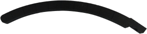
A long arm is an accessory for the inflatable transducer rings. It is required when combining rings to inspect larger diameter pipes in order to ensure the combined ring can successfully close and be secured on to the pipe. In some cases, the long arm can also be used to allow one ring to inspect pipe sizes slightly larger than the designed inspection size. For example, a 28″ EFC ring can be used to inspect an NPS 30 (DN 750) pipe.
For more info, you can refer to our spare parts for inflatable rings webpage.
| Transducer ring type | Radial Clearance |
|---|---|
| Compact | 38 mm |
| Inflatable EFC, HD and HT | 63 mm |
| Solid ring | 76 mm |
| HT Solid, HD Solid and Claw | 50 mm |
| Slinky | 25 mm |
Regular calibration and servicing is recommended for the GUL equipment to ensure that it is always providing quality results. For most Wavemakers, GUL recommends a three year calibration period. More details are available on the hardware calibration support page.
Most of our equipment is supplied with a one year warranty. It is possible to purchase an extended warranty for some sorts of equipment (for example the electronics). Please note that the warranty only allows for normal wear and tear of the equipment; it does not cover misuse of the equipment such as large drops or immersion in water.
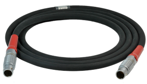
Off the shelf cables are typically 3 or 12m long. However, we offer cable custom lengths of up to 50 meters and can produce even longer ones if required for a specific application.
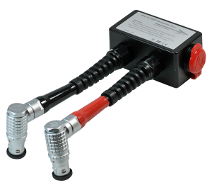
In order to inspect large diameter pipes, two rings can be joined together using the 16 to 8 Channel Converter Box (with the G4 Mini). If using a Wavemaker G4, up to 4 rings can be combined together.
For technical enquiries, please first check the support page. If you can’t find an answer there, please contact us at support@guided-ultrasonics.com.
For more information, please see GUL Software Updates webpage.
The TRUNK is GUL’s cloud platform that provides data storage and analysis services for our customers. This forms the back-end of the of the public facing Monitoring Studio and Scanning Studio web based platforms.
No, remote upgrading is not possible. In order to upgrade the firmware of a G4mini Base to a Full, the equipment would need to be returned to GUL(UK).
The GUL Screening results can be exported out to a variety of formats including Microsoft Word, Excel or PDF; export into other formats can be done upon request and discussion.
For technical enquiries, please contact us at support@guided-ultrasonics.com.
Typically, a Level 2 GULT qualified and certified operator is required to perform GUL Screening; Level 1 operators can assist a Level 2 operator(s). For more information on training, please see GUL Training webpage.


Step (1) : Download the Repair Request Form.
Step (2) : Fill up the required details in the form.
Step (3) : Email it to repair@guided-ultrasonics.com.
Step (4) : A GUL member will contact you once they have received and processed your repair request form.
After investigation of the equipment, we will normally provide a quotation for the repair and ask for a PO (and in some cases payment) before proceeding with the repair. We seek to repair all items within two weeks of receiving them in our office.
However, this may be extended if we do not have all of the required parts on hand, there are a lot of items to be repaired, it is a holiday week in the UK, or there are delays in getting approval for the repair.
Yes, GUL offer consultancy services on reviewing GUL Screening data. For a price quotation, please email your enquiry to info@guided-ultrasonics.com.
For more information, please see GUL Repair and Servicing webpage.
Check out the GUL Screening webpage.
Please send us a message on our Contact Us page. We will be happy to help.
For the G4mini battery MSDS, please see Battery MSDS.
For the G4mini CE DoC, please see CE DoC.