Studios
-
 Support
 -
 Contact us
 -
 News
News -
 Products
 -
0
 Cart
Cart
![]() Studios
Studios
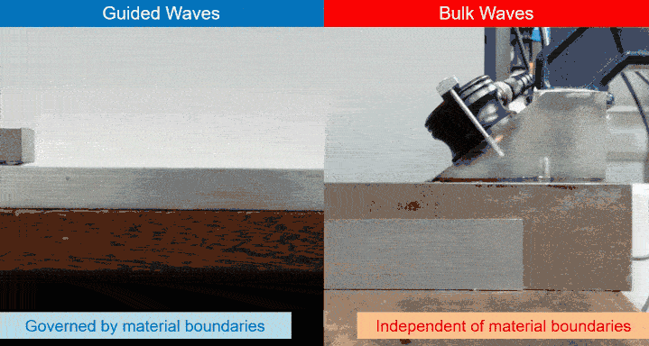
Guided waves are ultrasonic waves that propagate along a structure while being ‘guided’ by the geometry of the material rather than travel through the wall. This occurs at relatively low frequencies (around 25 kHz), when the wavelength of the signal is much larger than the wall thickness of the structure, allowing waves to propagate over long distances along pipes and other elongated structures.
For example, guided wave signals at 25 kHz have a wavelength of about 130 mm (≈5.118 in), while pipe wall thickness typically ranges from 3 mm to 40 mm (⅛–1.575 in). Because the wavelength is much larger than the wall thickness, the waves remain confined within the structure and travel efficiently along it.
In contrast, bulk waves propagate independently of the structure boundaries and travel through the material rather than along it.
Because guided waves are dependent on the geometry of the structure (such as pipes, plates, and rails), multiple propagation patterns, known as wave modes, can exist.
For pipeline screening, the two most commonly used modes are the Torsional T(0,1) and Longitudinal L(0,2) modes. These fundamental modes are analogous to the Shear and Compressional waves in conventional ultrasonic thickness testing.
")
")
Shear‑Horizontal (SH) guided waves propagate with particle motion parallel to the surface of the structure. These waves are especially sensitive to wall thickness variation and form the basis of guided wave scanning used for quantitative wall thickness measurement.
")
SH wave animation adapted from a simulation by J. Noguera, Universitat Politècnica de València (UPV). Source here.
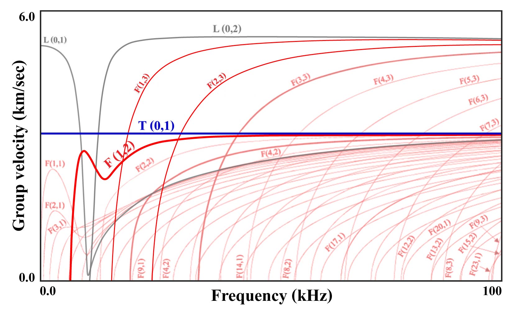
Guided Waves propagate along the pipe at velocities that depend on both the wave mode and the signal frequency. This behaviour is described by dispersion curves, which show how wave velocity varies with frequency for different guided wave mode.
The example shown is a set of dispersion curves for a 6″ Schedule 40 steel pipe, generated using the specialised DISPERSE modelling software. In this plot, the horizontal axis represents signal frequency (kHz) and the vertical axis represents the group velocity (km/s). Each curve corresponds to a different guided wave mode.
The longitudinal L(0,1), torsional T(0,1) and flexural F(1,2), F(1,3) and F(2,3) wave modes are fundamental for pipeline guided wave screening using GUL equipment.
In practice, inspectors do not need to interpret these curves directly. The physics behind guided wave propagation and dispersion, together with the extensive expertise developed by GUL, is incorporated into our software WavePro®, allowing inspectors to focus on evaluating the integrity of the structure.